Thursday, December 3, 2015

Motor and Transmission Mounts on a Chevy Prizm or 1998 to 2002 Toyota Corolla

I'm surprised to learn how many motor mount configurations there are for my 1999 Chevy Prizm.

What we have here is pictures of locally available motor mounts. I see that the 3 speed transmission (left picture) has a different motor mount than my 4 speed transmission. Then the center is the motor or transmission mount, which I should refer to to being over my transmission on the driver's side of the engine bay. I should inspect this one more closely for cracks or weakness.

The transmission mount on the right of the picture above is for manual transmissions.

On to the next set of mounts available for my car, and I'll get to my point:
On the left is the front motor mount (common name), but it literally is connected to my transmission. That is the correct one for either the 3 speed or 4 speed transmission like I have. The point is that the motor mount on the right is for the manual transmission. That's what I just pulled out of my 4 speed transmission car! I'm sure they bolt up the same or I wouldn't have been able to have the "wrong" one in, but now I'm relieved as it's broken that I'm getting the correct transmission mount installed.

The 2nd from the left motor mount is the only "true" motor mount on my Chevy Prizm. It's on the passenger side (in left hand drive cars) on the top/side of the engine.

2nd from the right is the motor mount (sorry, strong habit, it's literally a transmission mount), which I first noticed failed on my car. I've gotten a quality one from Toyota. Boy that was hard to get! Every sub part of that part is super high quality! Great steel, at least for how it looks and feels. Great rubber! Super good...then I looked closer at the welds. Those steel welds have something to be desired for strength, see my YouTube video below, "My New Motor Mount, long awaited, crappy welds!"

The locally available motor mounts have good welds at the moment, but the rubber is poor and I expect failure like before so I want to window weld them with 60 shore strength. Once drag racer of a Hyundai Elantra on the Jafromobile YouTube channel uses 80 shore strength, but seeing as how I can't find that and he has literally 4 times the acceleration that I have in my Chevy Prizm, I think 60 shore strength is plenty strong to plus up this lower quality locally obtainable part.

Sure, you may say, just get another one from Toyota (a Chevy Prizm is basically a Toyota Corolla), but that took a month, I'm not going 2 months without my car. The rear transmission mount is what is hours of work to get to the, the front one can be removed with much less subframe disassembly.

I'm working literally on uploading a video to show the Toyota, USA made motor or rather transmission mount as you read. :)


Here's my uninstallation of the front and rear motor mounts:


The next video I'm in the process of editing is a motor mount inspection video and half of the installation. What are different problems they can have? Failed welds, sure, most commonly the rubber gets cracks. Some cracking with age can be okay if the engine still is held firmly in place when you brake torque the engine. That's where you put the car in drive or reverse, hold the brake, and press the gas some. The engine should move some, but mine was flopping like a fish!

Motor Mounts Front & Back Installation Part 2:


Source: Motor Mounts Front & Back Installation Part 2 of 3 by DENichols


Motor Mounts Front and Back Installation part 3 Finishing End links mostly:


I'm embedding the part 2 video in my article when I last brought up replacing at least one of the same motor mounts! Shocks, Struts and the Steadiness of Your Car or Truck

By AutoBravado

Wednesday, August 26, 2015

O2 Sensor Upstream Diagnostics

Upstream O2 sensors should switch up and down across 450 millivolts. Above 450 millivolts or .45 volts is rich and below is lean. This should be on a .1 to .9 volt scale. I've seen oxygen sensors that were getting stuck lean. Fuel trims kept going up and up until they were maxed. At this point the O2 sensor would finally read rich and get even above 1 volt. As fuel trims decreased the graph would flatline again.

Upstream O2 sensors defined:

This is the O2 sensor which is the first to see your exhaust off the manifold. Because it's before the catalytic converter it's "upstream". Modern cars replace upstream O2 sensors with Air/Fuel sensors which can see a broader scale across versus seeing just barely up and down from the rich/lean that a catalytic converter needs to stay healthy.

I've had trouble for the last year with a running rich condition at idle. The OEM sensor I chose was reporting below 100 millivolts. While further experience with it's warranty replacement shows that oxygen sensors do indeed go below 100 millivolts, or at least it does from the manufacturer Denso, most of the time that it would operate in this range, it's before the engine has heated up and the engine has gone into closed loop operation.

Closed loop operation:

This is a condition where the PCM (Powertrain Control Module) has determined that the conditions are set that the information from the O2 sensor can now be deemed reliable (it's gotten hot enough). My vehicle would usually be in closed loop instantly. Normally, you want to be in closed loop as soon as possible. It uses less gasoline and helps with your car's mpg. This was too fast. Even though my heater circuit was 15 ohms; same as my warrantied replacement, that really isn't a complete test and I suspect that the heater core had a problem that my PCM couldn't detect.

A full test would be to have the heater in heating operation and see what the voltage drop is, but I doubt that's a procedure I could get specs on. Ohm meters use very little current. When you have more current something that looks right can suddenly test poorly. Only 1 fragile wire for example could show that a battery cable is good on an ohm meter, but it couldn't carry enough current it and it would show voltage drop when you place leads on each end of it. The voltage measured is the mount of voltage lost to that wire out of the available voltage from a battery for example.

Something I notice my PCM doing when it doubts if it has a good O2 sensor, is that it'll run rich and instead of switching back to lean like it should, it'll go even richer for a moment. This is s a test to ensure correct operation. If it keeps going richer the O2 sensor is failing the test. If it goes lean after this brief test it passed.

Realize you have to have a good testing method:

I typically rely on live scanners. These devices plug into the OBDII port, can pull trouble codes, and can show live streaming data. Except it's really not live streaming data. It shows a timeline sure, but the information isn't updated frequently to rely be "live". Such methods are fraught with difficulty when it comes to O2 sensors. O2 sensors and PCM's are communicating far faster than the live data from a scanner shows. Until an O2 sensor has gotten very bad, it can be difficult to diagnose. 

Plugging into the wiring directly from a DVOM isn't accurate either. It's sampling rate isn't bad, but it averages the data it receives and switches the screen slowly. Part of this design is intentional. You can't really see a screen and have it processed in your mind if it switched faster than you eye can see. 

An oscilloscope would be my next diagnostic tool, but they are spendy.

The catalytic converter link I put above links to my article about beating the P0420/P0430 diagnostic code. It'll also give you insight into downstream O2 sensors.

Also check out my newer article about the oxygen sensors 4 stages of death.

Check out my YouTube video for a downpipe modification that made my O2 sensor go in much easier to my 1999 Chevy Prizm (usually same as 1998-2002 Toyota Corolla). I also talk about some diagnostics that were specific to this situation.


Written and produced by AutoBravado.

Wednesday, March 25, 2015

Head Gasket repair on a 1999 Chevrolet Prizm

I had the loveliest surprise last week when I discovered that my 3 years of minor oil leaking was actually coming from my head gasket.

It's common on the 1998 to 2002 line of Chevrolet Prizms for there to be an oil leak on the passenger backside of the engine. It's not leaking there. There's a seal there, that I believe comes with a timing chain set. I've had the timing chain tensioner and seal for a year or so, just not getting around to this minor leak.

If you've seen any of my blogs like www.autobravado.com or carmilespergallon.blogspot.com you'll see articles relating to much more important repair in the last five years. It's leaking squarely on the passenger side of the engine, not front or back, very close to the serpentine belt tensioner. At this height there's just nothing else it can be. It's the head gasket.

Now if you check out my milky oil cap article and a video attached from a fellow mechanic you'll know exactly what I'm not seeing. I see no evidence of any oil or coolant being mixed in the oil, the coolant, or out the exhaust.

I have had a slow decline in my car's mpg from the low 30's in the city to 27. (27 is a new low, hadn't seen worse than 28 in a LONG time.)

Compression is still good and within normal limits. I just bought my own compression tester and leak down tester so that I can redo this specifically being sure that there's nothing deeply wrong other than a small oil leak. This oil leak doesn't even have the decency to get on the ground unless I'm in a Southern Utah summer where the engine is warmed up when I turn it on when it hadn't been on that day yet. So for all but summer, I about forgot about it every year until I had a problem with my transmission that was beyond my abilities.

The owner commented, "It's a mess under there." Wounded, I cleaned up all the grease all over from something I repaired which REALLY leaked badly and I had never cleaned it up. After spending a few hours making things prettier that most people will never see, the next day I look and now I'm aware of this oil leak...

....I've spent days online buying and buying for what I'll do while the cylinder head is off! All I'm saying for now!

If you like, the best hint I'll give is series of pictures of things I'm buying:


June 2015 update for HP when my engine bay is heat soaked:

50 MPH HP run with the fully family. See how the PCM allows higher RPMS only when there is greater load? It'll shift much earlier with less weight in the car:
This upgrade idea seemed tempting, but it's missing the flex the exhaust needs to help protect the engine. The engine is supposed to move some to protect the transmission. The only way to add a flex pipe, would be to add it after the catalytic converter, and that's too little too late.

Okay, the following pictures reveal what all the tool upgrades above are for. A port and polish:

Above points out some land marks on this cylinder head. Of course the intake and exhaust will get get smoothed from their original casting. They'll also get opened up some, how much depends on an ultrasonic metal thickness tester, which I also need to purchase, to know where the intake and exhaust runner are thin and can't be opened up.

The machinist ridge makes some of the most important differences in flow. Without removing it and blending it, the intake and exhaust valves have to open a great deal more for flow to really start. As the fuel mist from the fuel injectors hit the machinist ridge, the mist/fuel droplets tumble and hit each other causing them to get bigger and get a less complete burn.

9/22
A book recommended to me by Hugh O'Brien per our discussion on the Jafromobile channel:

Hugh explained this book will help me with the unique problems 
with porting and polishing 4 valve heads. 

The information Hugh gave me has been incredible. For example, NA heads don't need the bowl side of the valve opened as much has force inducted engines - 3/16". The burrs I was choosing above were terrible choices. I need single cut burrs, preferably with 6 inch shanks so I can see what I'm doing. The trouble I'm having is I can't find any diagrams of where the coolant jackets are so I know what I can remove and work with. Also, the clyinder style burrs are terrible as they will leave scratches. I'll need to work with single cut carbide burrs only, oval and elongated only.


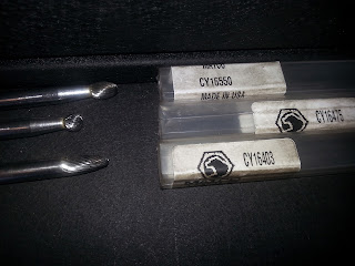
Recent update included pictures of good single cut carbide bits instead of double cut which are too hard to clean. I took down the cheap eBay carbide bits pictures. Here's some part numbers if you want them all, but if you only want one, I think I mixed up the packaging. Couldn't tell you which is which, lol.

Feb 22, 2016 Update:

This is not where I thought this would end...(for now, I'm taking the engine a part and the series has more to go with a part 6 coming out soone!).
 by AutoBravado

For the latest on this project, check out my next article, and remember that there's another half article after that!

Saturday, February 28, 2015

Misfires, fuel, ignition, or timing on P0300, P0301, P0302, P0303, P0304, or shall we say P030x?

Something I catch with my ear that ECU's* cannot. I listen with a screw driver or my favorite socket which is larger than most people's breaker bars. It's large and it reduces the volume of outside noises. I close the ear flap of my ear with one end to also deaden outside noises. I listen to each spark plug as best I can - of course with them all running.

Whichever sounds brighter is typically running strong enough or "on time". Whichever is sounding duller is late or weak. If I can't listen on the spark plug coil or wire, I'll listen as close as I can to the combustion chamber. Sometimes on the intake side, sometimes on the exhaust for where I can reach.

Coils that are bad can make a little electric crackle. The test above is comparable to an ECU counting misfires on a cylinder, except that it catches much smaller problems that may not come up as a misfire yet. It may not be bad enough. It, like the computer check for misfire can't distinguish between spark plug wire or coil on spark plug setup, not for sure what cylinder is misfiring.

Like I listen for a misfire the computer can mistake an echo. When I'm evening the spark out across an engine on a V engine what sounds bad on 1 bank may be a problem coming from the other bank opposite of the cylinder on the V. If in the firing order the previous cylinder doesn't have good enough spark, the next cylinder will sound weak when it may have been strong.

Long story short, this is why ECU's can get which cylinder is misfiring wrong. This video has a very effective way of ruling out more than one problem at once. Logically, I recommend it in a coil on spark plug setup over a spark plug wire to spark plug setup, as the chances of mixing up spark plug wires is much higher.

Thank you for inspiring this article Shrodinger's Box:
P0304 misfire Quick Diagnosis with just CodeReader-no scan tool
by AutoBravado

On my own cars and trucks, I usually get rid of a "misfire" before it's significant enough to show up as a check engine light issue. I'm making engines run smoother, and it really is a bit of a misfire, but not enough for the PCM to declare emergency with a blinking Check Engine Light (CEL). I show these techniques here: